

How to Choose a Lens for Barcode and QR Code Scanning
A barcode reader can use a fast processor and a high-resolution sensor and still fail to decode a code reliably. The code may be too small in the image, blurred by motion, distorted near the edge or poorly illuminated. The lens is one of the components that determines whether the camera captures enough usable information for the decoding software.
Choosing a lens for barcode or QR code scanning is therefore not simply a matter of selecting a wide field of view or matching the sensor's megapixel count. The designer needs to understand the code size, working distance, scanning area, camera position, motion, lighting and available mechanical space. These factors define the optical requirements together.
This guide explains the main parameters and provides a practical checklist for engineers developing fixed barcode readers, handheld scanners, logistics equipment and embedded vision systems.
1. Begin with the code, not the lens catalogue
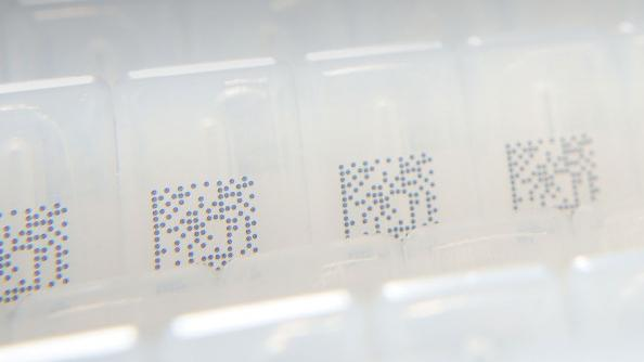
Before comparing lenses, identify the smallest code that must be read. For a one-dimensional barcode, the narrowest bar or space is a key feature. For a QR code, the smallest square element is commonly described as a module. The image must reproduce these features with enough contrast and sampling to allow the decoder to distinguish adjacent elements.
A code that occupies a large part of the image is generally easier to resolve than the same code captured from farther away. But increasing magnification reduces the field of view. The design must therefore balance the area that needs to be covered against the smallest code feature that must be decoded.
Record the code symbology, minimum module or narrow-bar width, print quality, surface condition and expected orientation. Include damaged, curved, glossy or low-contrast labels if they are part of the real application. A clean sample label on a bench is rarely a sufficient acceptance test for a logistics environment.
2. Calculate field of view and working distance
Field of view describes the width and height of the scene captured by the camera at a given distance. It depends on focal length, sensor dimensions and object distance. For a simplified thin-lens estimate at distances much larger than the focal length, horizontal field of view can be approximated from the sensor's active width and focal length. The exact result should be calculated with the lens model and confirmed in the final assembly.
Working distance is measured from a defined mechanical or optical reference to the target plane. Be precise about the reference point, especially when the camera is recessed behind a cover or mounted at an angle. A small change in working distance can alter both the field of view and the apparent size of the code.
For a fixed scanner, define the nearest and farthest target positions, not just one nominal distance. For a moving conveyor, also define the region in which the code may appear and whether the camera must read it across the full width. A lens that covers the entire conveyor may leave too few pixels across the smallest code at the far edge.
3. Understand pixel density and code module size
The sensor's pixel count is not the same as the number of pixels available across the code. What matters is how many sensor pixels represent the narrowest feature or QR module at the target distance and image position. If a code module is projected onto too few pixels, the decoder may struggle even when the overall image looks sharp to a person.
A useful design process is to estimate the physical size of the smallest code element, calculate its projected size on the sensor and compare that with the decoder's requirements. The exact minimum depends on the symbology, print quality, contrast, image processing and decoding algorithm, so avoid relying on a universal pixels-per-module number. Establish a target with the software provider and verify it experimentally.
Resolution should also be evaluated across the field. A code near the edge may be larger or smaller depending on camera geometry, lens distortion and perspective. If the camera is mounted at an angle, the far side of a flat label may be at a different effective distance from the lens. The optical design must support the worst-case location, not only the center.
4. Depth of field and focus tolerance
Depth of field is the range of object distances that appear acceptably sharp under a defined viewing or measurement criterion. A barcode reader may need to decode labels at different heights because packages vary in size or travel on an uneven conveyor. A handheld scanner may encounter codes at different distances as the operator moves the device.
A smaller aperture can increase depth of field, but it also reduces the amount of light reaching the sensor. This can require a longer exposure or higher sensor gain, which may be undesirable when objects are moving. A larger aperture collects more light but generally reduces depth of field and may make focus tolerance more demanding. The best aperture is therefore tied to illumination, motion and required sharpness.
Do not assume that a nominal focus distance guarantees acceptable decoding over the full working range. Test the smallest code at the nearest and farthest positions, including the edges of the field. If the scanner has autofocus or adjustable focus, verify response time, repeatability and reliability under the expected operating cycle.
5. Motion, exposure and illumination
In a conveyor or sorting system, the code may move during exposure. Motion blur can smear narrow bars or merge neighboring QR modules. A shorter exposure reduces blur, but it requires sufficient illumination or a more sensitive imaging system. The lens aperture, light source, sensor sensitivity and exposure strategy should be designed together.
Lighting should produce stable contrast without strong reflections. Glossy labels, shrink wrap, curved packaging and metallic surfaces can create specular highlights that obscure part of a code. A lens cannot solve every reflection problem, but its field of view, working distance and position affect where reflections appear. The lighting geometry may need to be changed, diffused or polarized depending on the surface and application.
For a fixed reader, test under the actual light source and ambient conditions. For a handheld device, consider sunlight, indoor lighting and changes in operator angle. Evaluate the complete camera rather than relying on a lens-only image under ideal laboratory illumination.
6. Distortion, edge performance and perspective
A wide-angle lens can cover a large scanning area, but it may introduce more geometric distortion than a narrower lens. Distortion changes the apparent shape and spacing of features across the image. Decoding software can often tolerate some geometric variation, but strong distortion, poor edge sharpness or uneven illumination can reduce the usable scan area.
If codes can appear near the image boundary, assess resolution and contrast at those positions. MTF data can help describe how well the lens transfers contrast at different spatial frequencies and image heights, but it should be interpreted with the sensor pixel size and code feature dimensions in mind. A single center-resolution figure is not enough.
Perspective is another issue. If the camera views a label obliquely, the code may be compressed in one direction. The lens may be optically sharp, but the projected modules become smaller and less square. Whenever possible, keep the camera close to the intended viewing axis. If that is not possible, validate the maximum angle and the decoder's perspective-correction capability.
7. Mechanical integration and environmental requirements
Barcode readers are often installed in tight spaces around conveyors, kiosks, handheld housings and automated equipment. Confirm the lens mount, barrel diameter, total track length, back focal distance and clearance to the protective window. The camera housing must not clip the required field of view, particularly at the corners.
If a protective window is used, include it in optical testing. The window can introduce reflections, reduce transmission or affect image quality depending on its material, thickness, coating and position. Dust, cleaning agents, vibration and temperature may also influence the final module. For industrial applications, specify the actual operating environment and required validation rather than assuming a general-purpose camera lens is sufficient.
For high-volume equipment, repeatability matters. Focus setting, lens retention, sensor alignment and mechanical tolerances should be controlled so that units behave consistently. A design that works only after careful manual adjustment may create yield and service problems when scaled.
8. A practical lens specification checklist
A useful request for quotation should include the sensor model, active resolution and pixel size; barcode symbology and minimum feature or module size; horizontal and vertical scanning area; nearest and farthest working distances; camera mounting angle; target speed; illumination type; and available mechanical envelope.
Also state whether the target is stationary or moving, whether codes may be glossy or curved, whether they can appear at the field edge, and what read-rate or verification standard the system must meet. Ask for field-of-view calculations and image-quality evidence at representative working distances. If possible, provide sample images or physical labels that represent the most difficult expected cases.
A good evaluation plan should include the smallest code, worst-case distance, highest target speed, lowest expected contrast and most difficult label surface. Measure not only whether one sample can be decoded, but how consistently the system reads across the entire operating region.
Working with Boshi Optics
Boshi Optics' published camera lens range includes compact fixed-focal-length configurations for security and embedded imaging, and its product information describes applications such as industrial inspection and logistics barcode reading for selected lens designs. The [camera lens product range](https://www.lensmanufacture.com/products/lens.html) is a useful starting point for reviewing available configurations. For a project with unusual field-of-view, working-distance or package requirements, the [customized optical products page](https://www.lensmanufacture.com/customized-products) outlines the company's custom optical capabilities.
When contacting an optical supplier, send the sensor details, code dimensions, scan area, working distance and mechanical drawing together. That allows the supplier to assess whether a standard lens is suitable or whether a customized optical design should be considered.
Conclusion: design for the smallest code in the hardest position
A barcode or QR code scanner lens should be selected around the smallest feature that must be resolved, at the most difficult working distance and image position. Field of view determines coverage, pixel density determines how much information the sensor samples, depth of field manages distance variation, and exposure and lighting control motion and contrast.
The most reliable process is to define the real scanning envelope, calculate the optical starting point, then validate the complete camera with representative labels and operating conditions. A lens that produces a pleasing general image is not necessarily a lens that reads every code reliably. The right lens is the one that delivers enough usable detail throughout the required scanning region.